Recently a colleague mentioned that Luatos Mall was running a promotion for the AIR32F103 BluePill development boardhttps://wiki.luatos.com/_static/bom/BluePill.html). At 9.9 RMB you get a board plus an extra AIR32F103CCT6 chip. I had never used STM32 MCUs before, so I picked one up to study, at least as a collectible.
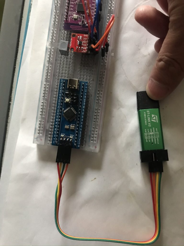
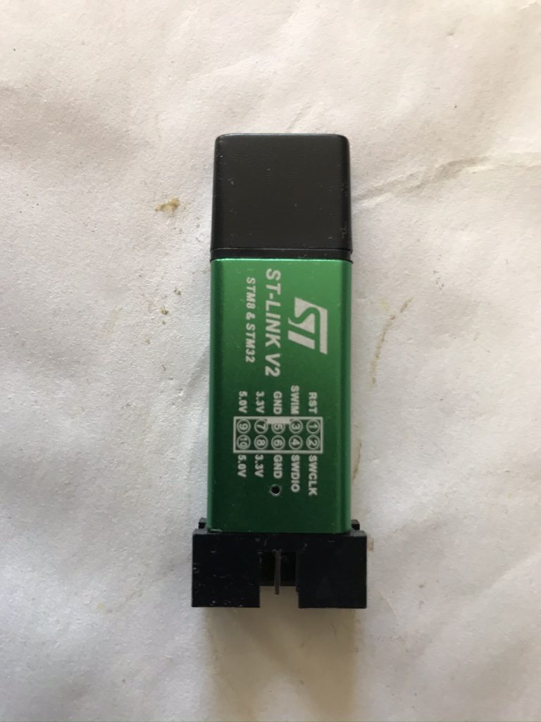
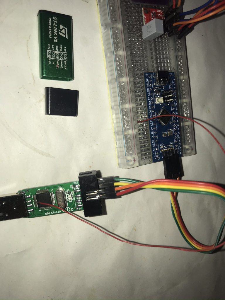
After receiving it, I quickly learned from Luatos documentation and searched for STM32 beginner guides online. I discovered various ways to upload programs. Since I had previously bought an ST‑LINK V2 (originally intended for flashing firmware to a WY815P soldering station), I chose to test using ST‑LINK SWD. After soldering headers and wiring according to the silkscreen, the PC recognized the debugger with STM32 ST‑LINK Utility. I then installed the research version of Keil (v5.23 from the netdisk bundled with the ST‑LINK), added the AIR32 software library per Luatos wiki, learned GPIO basics, and successfully lit the onboard LED. At this point I realized how much simpler Arduino is 😂. Breakpoint debugging in Keil also worked. But then I hit a problem: unlike Arduino Nano, which can easily use the IDE serial monitor for logs and command‑line interaction, this setup had no simple way to view printf output. So I spent time researching.
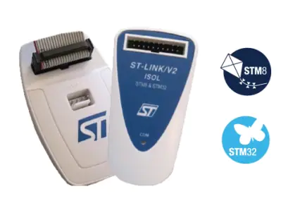
I found that my ST‑LINKs were all clones. The official version looks like this: https://www.st.com/en/development-tools/st-link-v2.html
淘宝上搜索了下,确实也有卖的,不过一个购买一打山寨版了。于是又去另谋他路,后来查到其实我朝的山寨ST-LINK V2其实还是很受国际友人欢迎的,同时也发现有人遇到了和我现在一样的问题,并提出了一种解决方案,就是SWD其实并不只是SWDIO,SWDCLK,还有一根可选的SWO接线,接上后就可以使用ST-LINK调试状态下的log查看:
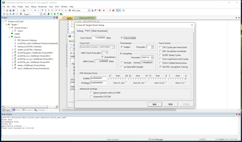
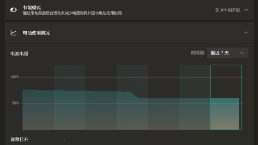
This corresponds to Keil’s Trace feature. Setup details are widely available online. The next problem: my clone ST‑LINK V2 had no SWO pin exposed, so hardware modification was required. I followed this article: Completion of the Chinese ST-Link v2: add the SWO debug information output interface and foot reset – https://sudonull.com/post/20076-Completion-of-the-Chinese-ST-Link-v2-add-the-SWO-debug-information-output-interface-and-foot-reset. The complexity was acceptable: just one jumper wire. I did not need hardware reset or extra power/ground pins, so I started.
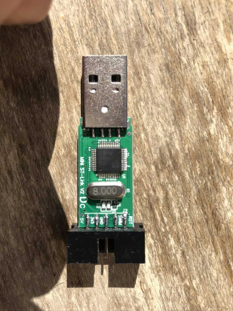
Opening the case confirmed it was a clone. The chip was not ST, but a Geehy APM32F103 MCU from Jihai Semiconductor. The datasheet showed full pin compatibility with ST. Following the reference article, I located the correct pin and soldered a jumper wire. Since I had experience with PS2 direct‑read mods, this was familiar. I did not scrape PCB traces (there were none under my board anyway 😂), just soldered directly to the pin. As long as you avoid pulling too hard, it works. The result:
Testing showed SWO output was visible. Note: the Trace frequency must be set correctly, and for AIR32 you must configure JTAG remapping properly (this chip has its own quirks, which I will document separately).
Finally, I noticed that the through‑hole above the LED was perfect for routing the jumper wire out, while still allowing the LED light to be seen. So the modded ST‑LINK V2 clone ended up like this:
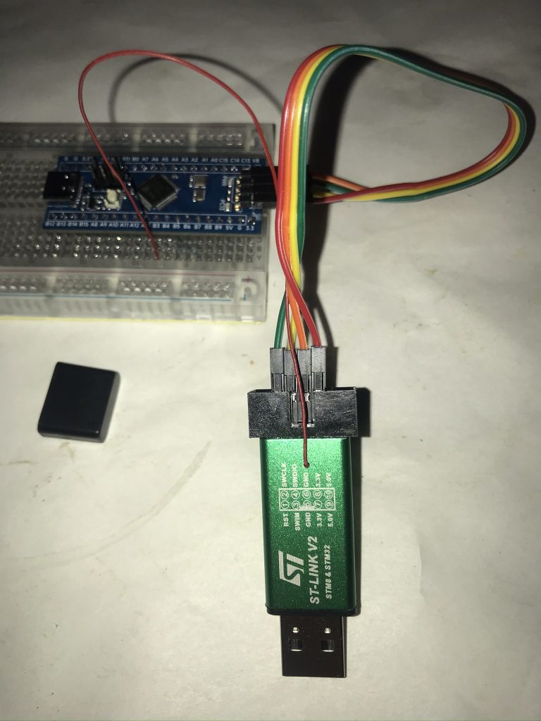
This way you can keep using the cheap clone but still unlock SWO logging support in Keil.
博主友情提示:
如您在评论中需要提及如QQ号、电子邮件地址或其他隐私敏感信息,欢迎使用>>博主专用加密工具v3<<处理后发布,原文只有博主可以看到。