Since replacing it with the Redmi AX6000 last October, the Y1S that had served for nearly 10 years finally retired and has since been sitting unused in a box…
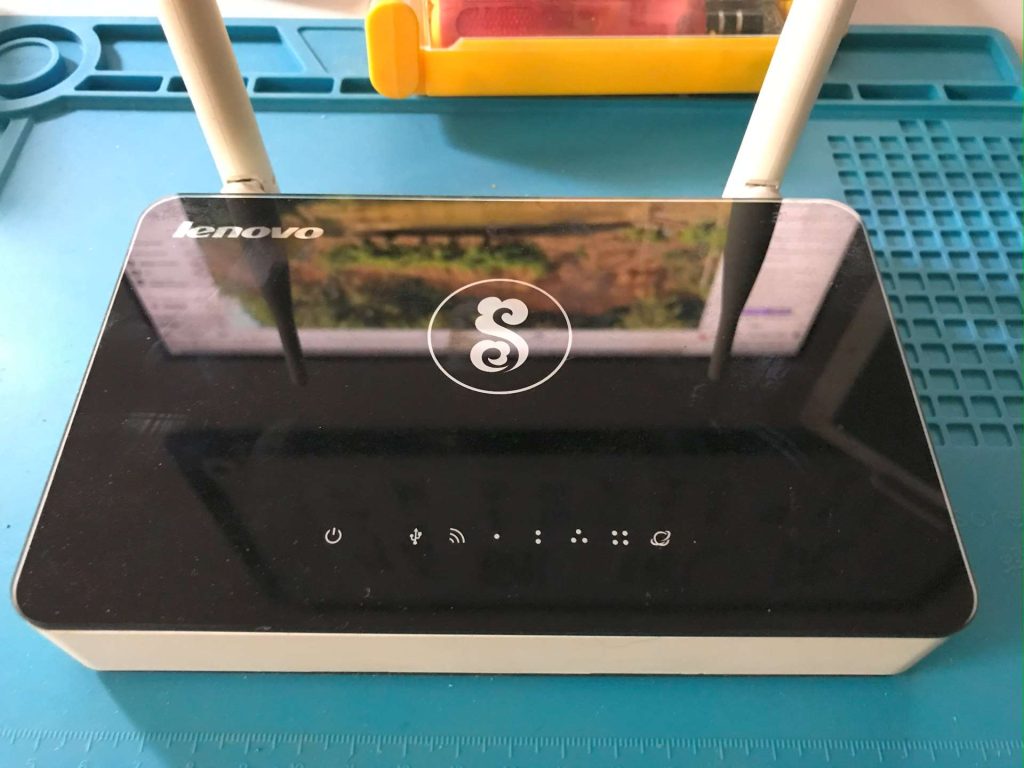
Until recently, while browsing the Enshan forum, I accidentally saw a post by user 1421890054: 【2022-1-22】折腾一下OpenWrt-Lenovo-newifi-y1s-R22.1.1-mt7620a-USB, and realized that the Y1S can actually support larger flash chips (the original Winbond 25Q128 is only 16M, and after installing OpenWrt there is basically no room for software…). So I dug out the retired Y1S, planning to try a hard‑mod flash upgrade for fun.
Thanks to the forum post, I did not bother researching which flash chips are compatible, and directly bought two pieces each of MX25L25645GM2I and MX25L51245GMI from Taobao:
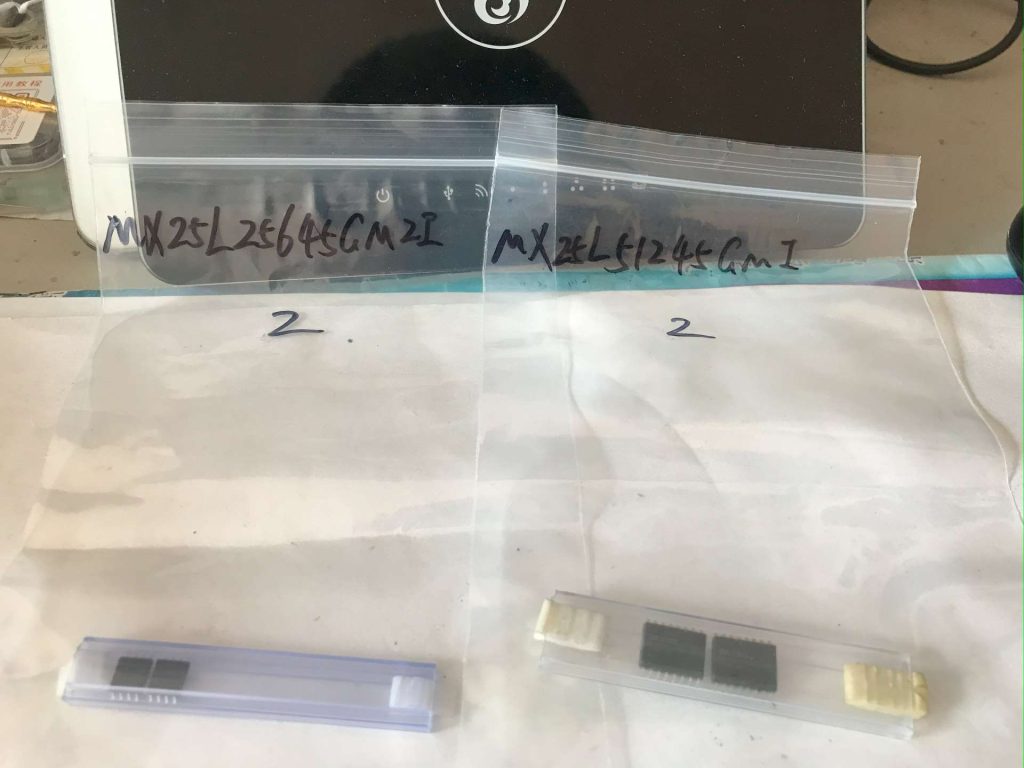
One chip cost 6 RMB plus 4 RMB shipping, my electronic component collection grew again 😂. Since I bought them before the Spring Festival holiday, they arrived quickly, but buying the programmer later was delayed by the holiday.
After receiving the flash chips, I noticed the 32M version ends with -10G, while the 64M is -08G, which differs from the -10G mentioned in the forum post. So I checked the datasheet: https://www.macronix.com/Lists/Datasheet/Attachments/8745/MX25L51245G,%203V,%20512Mb,%20v1.7.pdf
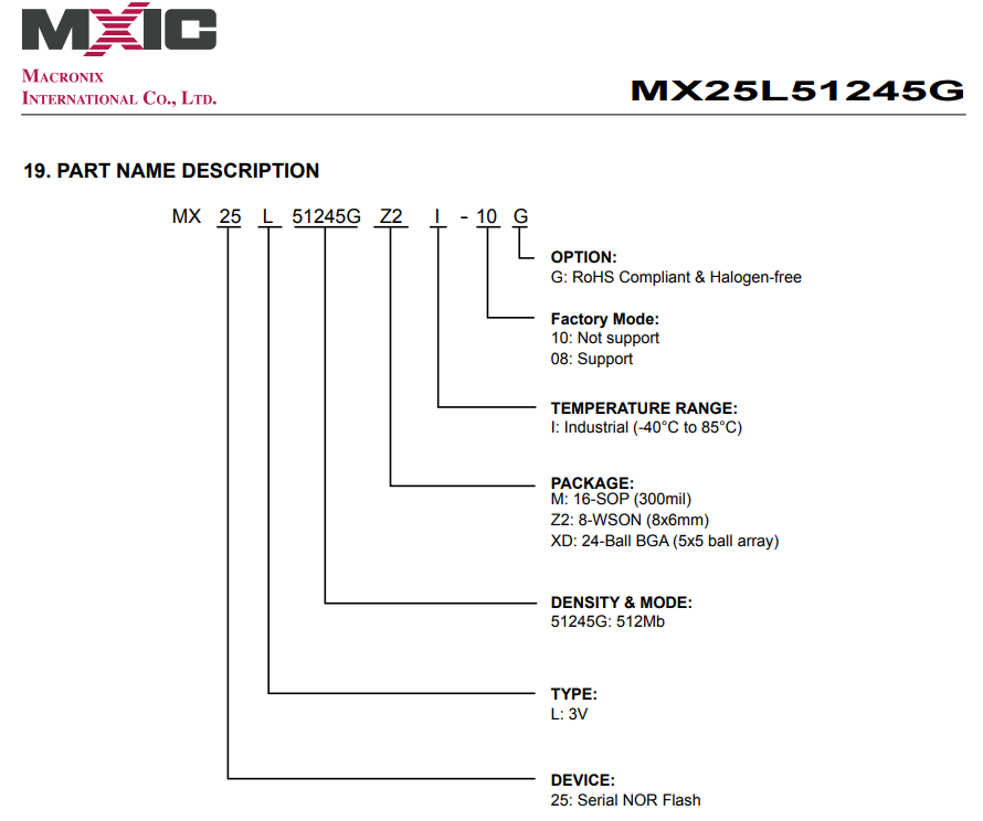
The difference between 08 and 10 is whether Factory Mode is supported. Reading the manual, it seems to be for mass production, irrelevant for hobby use. So I followed the forum author’s instructions: entered breed, backed up the EEPROM, took a screenshot of the MAC address modification page. Since this was my first time hard‑modding a router flash, I followed the prompts carefully, then backed up the programmer firmware:
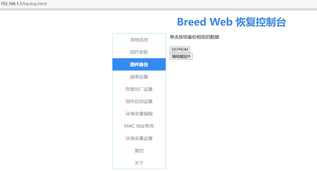
In fact, later the EEPROM backup and MAC screenshot were not used at all 🤣, only the 16M programmer firmware was needed. I also checked the current system info in breed:
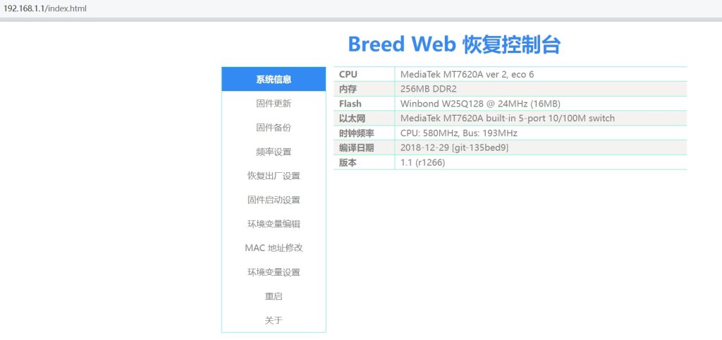
It showed the original flash was indeed Winbond 16M. Back in 2015 that was fine, but now it looks rather small…
Next, I began disassembly. There were teardown guides online from when it was first released. The process is simple: under the four rubber feet are four Phillips screws, remove them to open the bottom cover:
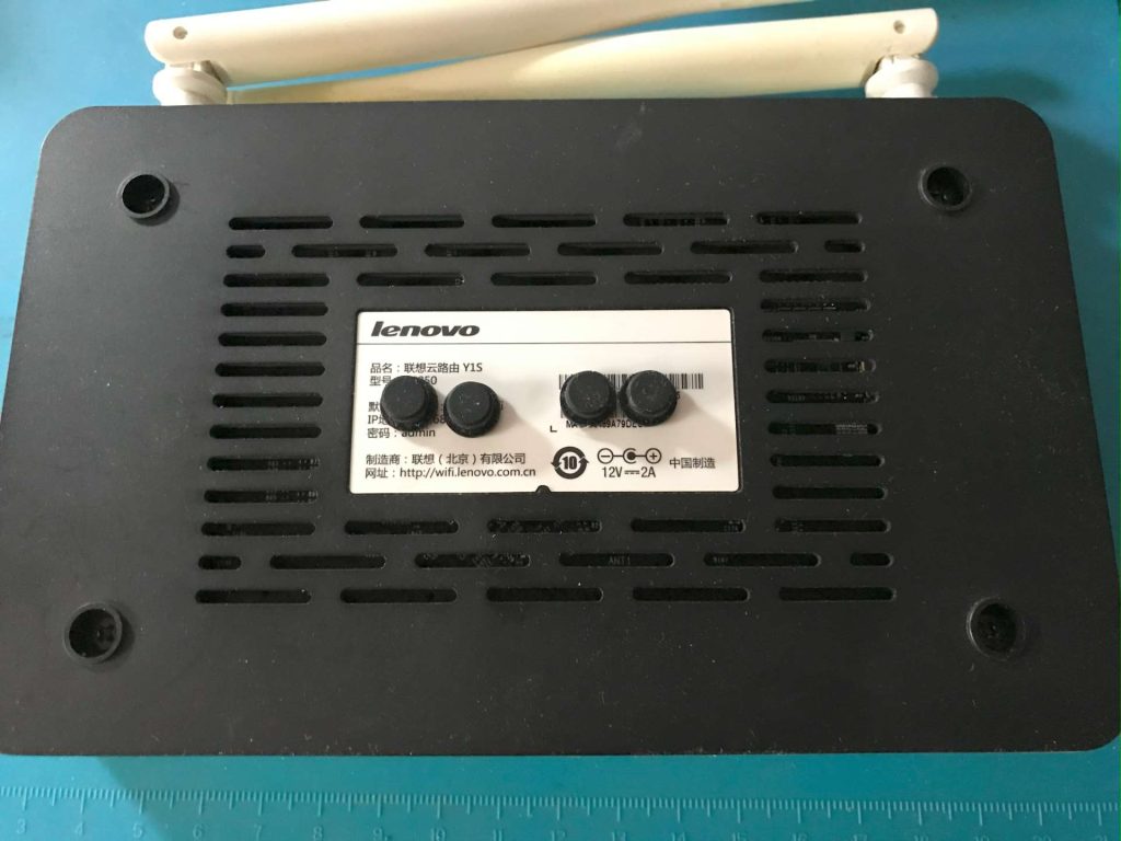
Opening it reveals the PCB. The flash chip is the SOP8 with a dot marking, near the lower right center:
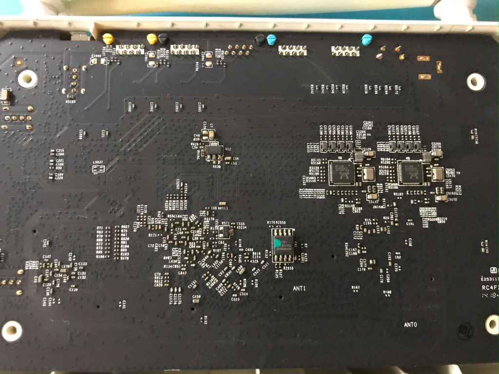
At this point you could desolder the chip directly (if confident in your skills), but as an amateur I removed the entire board:
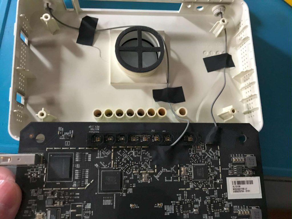
Be careful with the two antenna cables. The Y1S build quality is good, both PCB and connectors are well made. Carefully remove the tape, unplug the IPEX connectors, then the board can be taken out. For desoldering I used a WY815P hot‑air gun. To avoid blowing off nearby components, I taped the surrounding areas with high‑temperature tape:
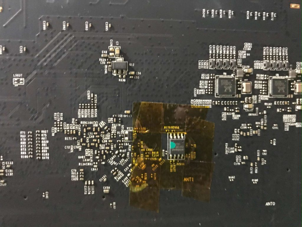
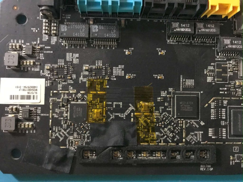
Then I applied flux, heated, and removed the chip:
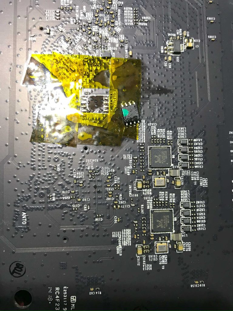
But due to lack of experience, the pads for pins 5‑8 were damaged. Later when wiring they came off. In hindsight I should have used the forum author’s method: use a soldering iron with leaded solder to mix with the original unleaded solder, making removal easier.
At this stage I thought the original breed bootloader was stored elsewhere (like CPU internal storage), so I directly followed the forum’s SOP8 to SOP16 pin mapping (also checked the datasheet):
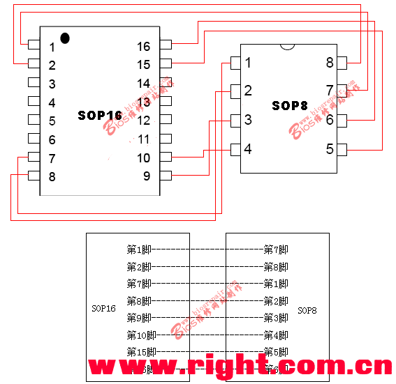
Boot failed, only flashing yellow LED (I forget which one). Holding reset while powering on did not enter breed. I realized a programmer was necessary (some people reportedly boot breed with the original flash, then hot‑swap to the new flash and flash directly, but I feared messing up, so I did not risk it). It was during the Spring Festival holiday, most Taobao shops selling programmers were closed. Finally I found one still open, bought a ‘gold’ CH341A programmer (actually CH341B, said to be the same, equally slow 😂) and SOP8 wide 200 mil 5.38 mm and SOP16 wide 300 mil 7.6 mm sockets. Shentong Express delivered in 3 days, almost normal speed, so thumbs up to Shentong!
After receiving the programmer, I saw the bundled driver and software were old, likely unusable on my Windows 11, so I deleted them. Searching Enshan, I found NeoProgrammer_2.2.0.10 maintained by Alangoa, with updated chip support: 【2024-1-31】芯片库更新 CH341A-NeoProgrammer软件添加芯片详细教程. After downloading, I foolishly installed the latest official WCH CH341 driver: https://www.wch.cn/downloads/CH341SER_EXE.html. NeoProgrammer then reported ‘connection error CH341 (Not found)’. Device Manager showed a WCH device called ‘usb to serial’ (I forget exact name), no warning icons. Thinking further, I realized NeoProgrammer includes its own driver (Drivers folder, with detailed docs and screenshots, great!). This driver is not the 2023 official version but from 2009. Perhaps that was the issue. I uninstalled the new driver, installed the old one, and indeed the programmer worked. Device Manager showed:
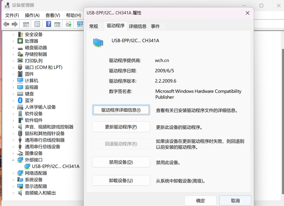
Identified as external interface, named USB-EPP/I2C…CH341A, clearly different from the latest driver, though both providers are wch.cn. Not sure why, but now the programmer was correctly recognized, so fine:
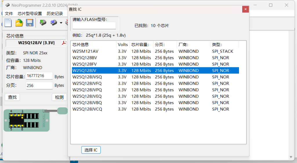
It detected the original Winbond 16M flash (I tried reading it, the beginning matched, but later data differed from the breed backup bin, not sure why, but I did not need it anyway).
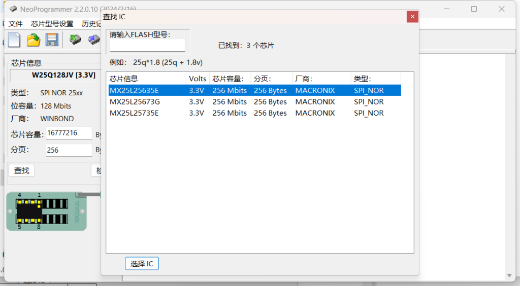
It showed MX25L25645GM2I as a different model, perhaps due to database mismatch, but selecting 25673G worked, reading 32M took about 5 minutes.
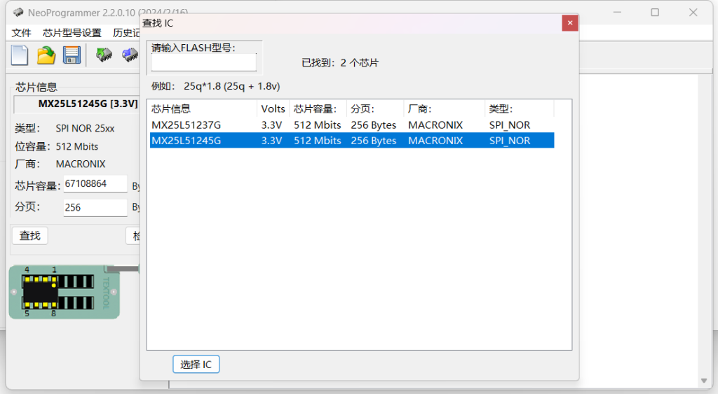
Finally the MX25L51245GMI was correctly identified, so I directly wrote the 16M breed backup bin into it:
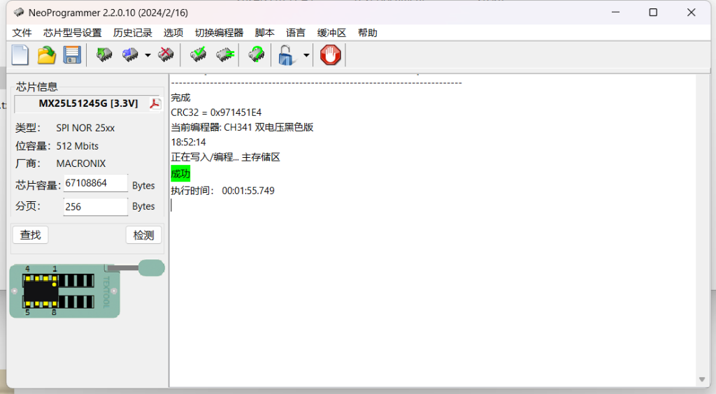
Writing 16M data took under 2 minutes, fine. But verification and read‑back took 10 minutes each 😂, the infamous CH341 slowness. Luckily the programmer is cheap, and I do not rely on flashing for a living, so fine. By the way, the SOP16 socket I bought converts to DIP16. According to the software pinout, only 8 pins are used, matching the mapping. The ‘gold’ package also included SOP8/SOP16 to DIP8 boards, but they require soldering, troublesome. I had male‑female Dupont wires, so I adapted the SOP16 socket myself:
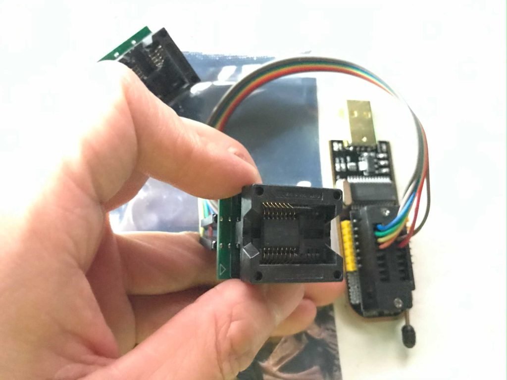
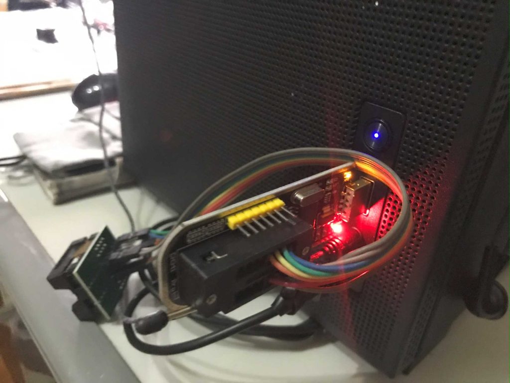
Successfully wrote the data, then wired to the router PCB. Due to earlier pad damage, I connected wires to nearby resistors and unused solder pads:
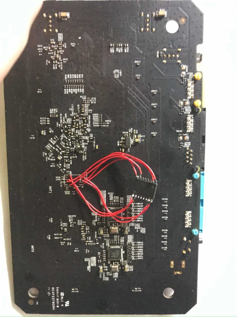
Power‑on test booted directly into OpenWrt, with the original 16M contents intact, everything normal. Reset into breed also worked, and like the forum post, it correctly recognized the 64M flash:
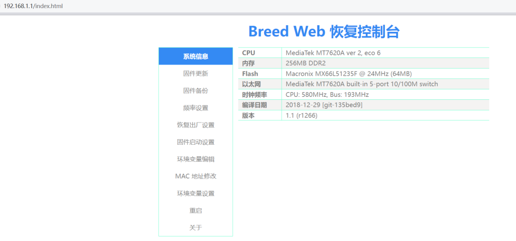
I confirmed the MAC address was unchanged, so the EEPROM backup and screenshot were unnecessary. Next I flashed the 64M firmware from the forum post. After reboot, startup felt slower, probably due to more bundled software, but it successfully entered the new OpenWrt system:
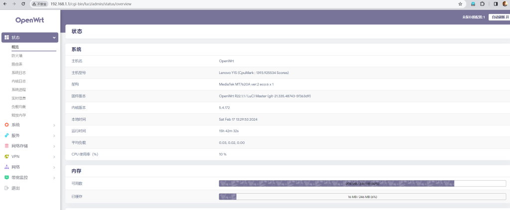
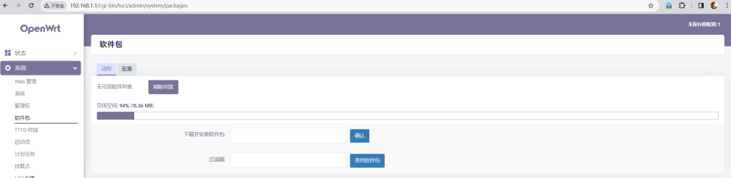

It showed about 15M free space for installing other software 😁. I tested wireless and wired, all normal. But unlike the Pandora version where the big logo breathing light
Finally, imitating the forum expert, I fixed the wired pads and flash chip with transparent tape:
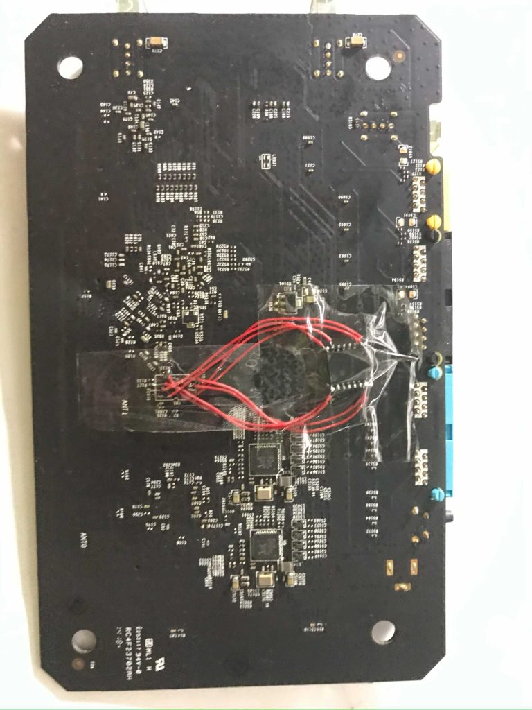
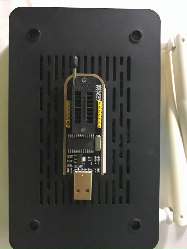
Finally, reassembled the case, completed the work, and took a photo together with the programmer.
博主友情提示:
如您在评论中需要提及如QQ号、电子邮件地址或其他隐私敏感信息,欢迎使用>>博主专用加密工具v3<<处理后发布,原文只有博主可以看到。